

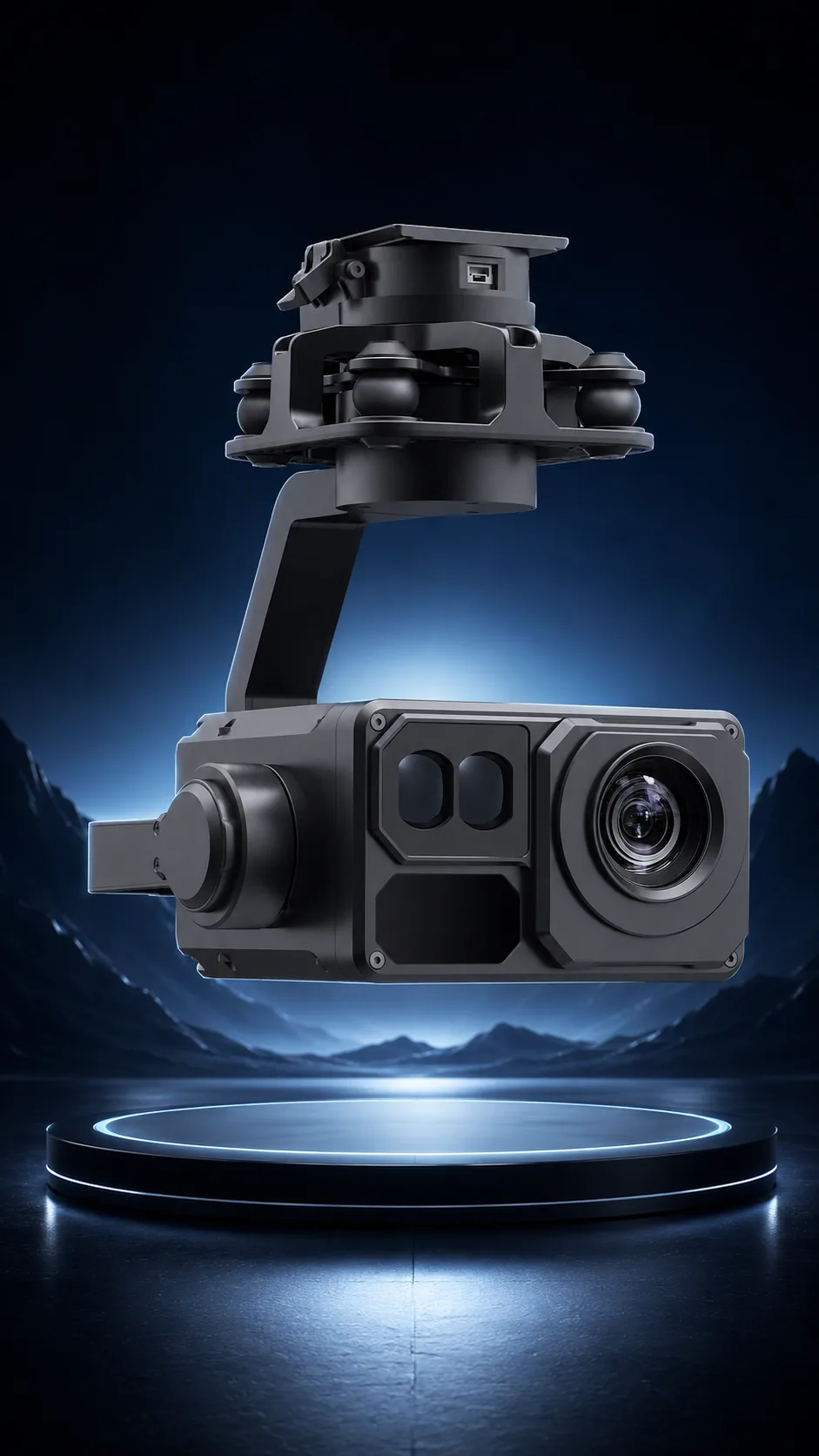
Most payload integration failures are not camera problems — they are interface assumptions nobody verified: connector pinouts, voltage ranges, control protocols and mounting resonance. This checklist front-loads those questions before you buy.
- 4 domainsMechanical, electrical, control, video
- 7.4–53 VRange across the line
- 3.4xTypical stall-to-static power ratio
- 1 questionPrevents the most rework
Key takeaways
- The largest failure class is buying the wrong link variant. Confirm the exact video link and flight controller before anything else.
- Size the supply for peak current at gimbal slew, not static draw — the published gap is often three to five times.
- Mechanical checks come first because they are the ones you cannot fix with a cable: mass and CG, mounting pattern, clearance through full gimbal travel, damping matched to prop frequency.
- One payload often serves two aircraft mechanically and rarely does so electrically without an adapter plan.
On this page
Mechanical
Mass and CG shift within airframe limits comes first, and it is the check most often done by eyeball. A pod that is within the payload mass limit can still move the centre of gravity outside the envelope, particularly on a forward-mounted or vertically offset installation.
Then the mounting pattern and damping plan. Bolt pattern compatibility is trivially checkable and frequently assumed; damping is neither. Vibration isolation has to be matched to propeller frequency — dampers that are too soft allow low-frequency oscillation, too stiff and they transmit the blade-pass frequency straight into the sensor. Vibration and damping design covers the frequency arithmetic, and payload mechanical integration covers mounts and balance.
Clearance through full gimbal travel is the check people skip and then discover in flight. A pod with ±360° continuous yaw and pitch travel to +70° will, at some point, be pointed at your landing gear, your antennas or your own propellers. Walk the full travel envelope on the bench with everything installed, not with the pod on a desk.
Electrical
Supply voltage range and peak current at gimbal slew are the two figures that matter, and the second is the one that gets missed. Published static and stall figures across the line show why.
| Payload | Operating voltage | Static / average | Stall or peak |
|---|---|---|---|
| AX-20S | 7.4–26.4 VDC | 1.0 W | 5.5 W |
| AX-20T | 7.4–26.4 VDC | 1.5 W | 14 W |
| AX-200T | 12–26.4 VDC | 1.7 W | 23.5 W |
| MV-2P | 10–26.4 VDC | 6.5 W | 20 W |
| OP-80U | 20–53 VDC | 6.5 W | 23.4 W |
| OP-90P | 20–53 VDC | 10.5 W (ranging off) | 55 W (ranging on) |
| LX-6U | 20–53 VDC | 5 W | 75 W |
| LX-9B | 20–53 VDC | 21.4 W | 50.4 W |
Note the LX-6U: 5 W average against 75 W stall, a fifteen-fold ratio. A supply sized for the average figure will sag when the gimbal fights wind or hits a travel stop, and what fails is usually not the payload but something else sharing the rail. Prefer clean power over a shared rail where the airframe allows it, and check connector type and locking — a payload that unmates in flight is a lost payload.
Cable strain relief on a moving gimbal is the slow failure. A harness routed without service loop works perfectly until several hundred yaw cycles have worked it against an edge. Payload power budgets covers wiring that holds.
Control and Data
Protocol match is the first question: S.BUS, PWM, serial, CAN, or ONVIF/IP as on the OP-80P. These are not tiers and not interchangeable — pick by who is issuing commands, as the interface comparison sets out.
Then channel mapping for pitch, yaw, zoom and photo. Do this on paper before ordering, including the functions you will want in six months rather than only those you need at first flight. Discovering that you are three channels short after the airframe is built is an avoidable and irritating rebuild.
SDK or MAVLink needs for autonomy stacks come last in sequence and first in risk. If a companion computer will drive the payload, the protocol document is the deliverable that matters and its quality decides whether integration takes days or months — see evaluating payload suppliers.
Video
Output format versus your link is where the largest single failure class lives. Digital ecosystems — O3, O4, O4 Pro — analog AV, and IP streams all expect different things, and the AX-20 series ships in O4 Pro, O4, O3, Avatar/Moonlight and AV variants precisely because a single universal unit is not physically possible.
A mismatched variant does not connect. It is not degraded performance that you can live with until the correct one arrives; it is a unit that does not work with your air unit at all. Matching a gimbal camera to your FPV link maps every variant against its ecosystem.
Latency budget for the operator task is the second video question. A control-room operator watching a scene does not notice 60–100 ms; a pilot flying proximity work by camera does. Decide by task rather than by the number — video latency budgets by mission breaks it down.
The Order to Test In
Sequence matters because each stage can invalidate the ones after it. Testing control before confirming power leads to hours spent debugging a protocol problem that was a sagging rail.
- Confirm the variant against your exact video link and flight controller — before ordering, not after delivery.
- Verify mass, CG and clearance through the full gimbal travel envelope with the pod installed on the actual airframe.
- Bench the electrical side: voltage range, static draw, and peak draw at slew, measured rather than assumed.
- Exercise control: every function through the intended interface, plus arbitration behaviour if you are combining S.BUS and serial.
- Check video end-to-end on the real link and ground station, and measure latency for your operator task.
- Fly with props running and inspect for resonance bands — the failure a bench test cannot reproduce.
Front-load the variant question. Of the four domains, video-link variant mismatch is the cheapest to prevent and the most expensive to discover. It is one email before ordering versus a deployment slip afterwards.
Standardising Across Two Aircraft
The ambition is reasonable and the constraint is electrical. One payload often serves two aircraft types mechanically — bolt patterns and mass budgets are frequently compatible — and rarely does so electrically without an adapter plan, because voltage ranges and connector conventions differ.
The published ranges show where the natural boundaries fall. The AX gimbals accept 7.4–26.4 VDC, the MV micro pods 10–26.4 VDC, and the OP and LX pods 20–53 VDC. A payload in the 20–53 V group will not run from a 4S airframe without conversion, and a 26.4 V-limited unit must never see a 12S bus.
Verify both mechanical and electrical before standardising, and treat the adapter as part of the design rather than a field improvisation. A hand-made adapter cable is the component most likely to fail and the least likely to be documented when it does.
Related reading
- Payload Mechanical Integration: Mounts, Damping and Balance
- Vibration and Damping Design: From Propeller Frequency to Image Blur
- Gimbal Control Interfaces: S.BUS, PWM, Serial and CAN Compared
- UAV Payload Power Budgets: Voltage Ranges, Peaks and Wiring That Holds
- Matching a Gimbal Camera to Your FPV Link
- Video Latency in UAV Payload Systems
- An Integrator’s Checklist for Evaluating UAV Payload Suppliers
- Payload Weight vs Flight Time: The Math Every Integrator Runs
- OP-80P — 4K spherical pod with ONVIF output
- AX-20T O4 Pro variant
- LX-9B — multi-sensor pod with ranging
- Telecom Tower Drone Inspection
FAQ
What single question prevents the most rework?
“Which exact video link and flight controller are you running?” Payload variants exist per link ecosystem, and matching them first eliminates the largest failure class in payload integration. A mismatched variant does not connect at all — there is no degraded mode to work around while the right unit ships. Asking this before the order costs one email; discovering it after delivery costs a deployment slip.
Can one payload serve two aircraft types?
Often yes mechanically, rarely electrically without an adapter plan. Bolt patterns and mass budgets are frequently compatible across airframes, but voltage ranges are not: the AX gimbals accept 7.4–26.4 VDC while the OP and LX pods want 20–53 VDC. Verify both domains before standardising, and design the adapter deliberately rather than improvising one in the field.
How much power headroom should I plan for?
Size for the published peak or stall figure, not the average, and add margin on top. The gap is larger than most people expect — the LX-6U publishes 5 W average against 75 W stall, and the OP-90P 10.5 W with ranging off against 55 W with it on. A rail sized for the average will sag when the gimbal fights wind or the rangefinder fires, and the component that misbehaves is usually something else sharing that rail.
Questions about the technology? Talk to our engineers — we reply within 2 business days.