

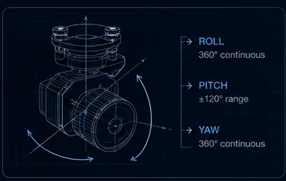
At 1,000 m standoff, a gimbal error of 0.01° moves your aim point 17 cm; an error of 0.1° moves it 1.7 m — the difference between holding a connector in frame at high zoom and losing the tower entirely.
- 17 cmError at 1,000 m from 0.01°
- 1.7 mError at 1,000 m from 0.1°
- 3 specsHiding inside “accuracy”
- ~30xWhere stability caps zoom
Key takeaways
- Angular error times range equals linear error. That single relationship is the whole subject, and it is why the same gimbal is excellent up close and useless at distance.
- Three different specifications hide inside the word “accuracy”: pointing accuracy, stabilisation jitter and drift. Long-lens work is limited by whichever is worst.
- Magnification multiplies apparent motion — 0.02° is invisible wide-angle and sweeps a large share of the frame at narrow telephoto.
- Past roughly 30x magnification, gimbal jitter rather than optics usually caps usable zoom.
On this page
The Arithmetic, in Centimetres
Pointing error is an angle, and an angle only becomes meaningful when you multiply it by a distance. The table below is straight trigonometry — no product claims, just what a given angular error costs you on target at realistic standoff.
| Angular error | At 100 m | At 500 m | At 1,000 m | At 2,000 m |
|---|---|---|---|---|
| ±0.005° | 0.9 cm | 4.4 cm | 8.7 cm | 17.5 cm |
| ±0.01° | 1.7 cm | 8.7 cm | 17.5 cm | 34.9 cm |
| ±0.02° | 3.5 cm | 17.5 cm | 34.9 cm | 69.8 cm |
| ±0.05° | 8.7 cm | 43.6 cm | 87.3 cm | 1.75 m |
| ±0.1° | 17.5 cm | 87.3 cm | 1.75 m | 3.49 m |
Two things fall out of this immediately. First, an accuracy figure is meaningless without a working distance — ±0.05° is entirely adequate for a camera looking at something 30 m away and hopeless for one reading a conductor at 1,500 m. Second, the difference between adjacent specification tiers is not cosmetic: at 1,000 m, moving from ±0.1° to ±0.01° is the difference between 1.7 m and 17 cm of wander, which is the difference between searching for your subject and framing it.
Three Different Specs Hiding in “Accuracy”
Vendors use one word for three distinct behaviours, and a payload can be excellent at one while failing at another.
Pointing accuracy is how close the camera aims to where it was commanded. This is a static, repeatable property — command 30° down, measure where it actually points, and the difference is your pointing error.
Stabilisation jitter is high-frequency residual shake: the small, fast motion that survives the stabilisation loop while the aircraft vibrates and gusts. It does not accumulate, but it blurs frames and makes a high-zoom image feel alive in an unhelpful way.
Drift is slow wander over time — the camera creeps off target across seconds or minutes as sensor bias accumulates in the attitude estimate. IMU, AHRS and attitude fusion explains where drift originates and why it is a harder problem than jitter.
Long-lens work is limited by whichever of the three is worst. A payload with superb pointing accuracy and poor drift will place the target perfectly and then lose it during a two-minute observation, which in practice is the same as not having found it.
Why It Compounds With Zoom
Magnification multiplies apparent motion. A given angular disturbance moves the image by a fraction of the field of view, and narrowing the field of view increases that fraction proportionally. So 0.02° of jitter is genuinely invisible at wide angle and sweeps a large share of the frame at narrow telephoto — the gimbal did not get worse, the lens made the same error matter more.
This is the mechanism behind a common purchasing disappointment. A payload bought for its zoom figure delivers unusable imagery at the top of its range, and the optics are blamed. Usually the optics are fine and the mount is the limit. Past roughly 30x magnification, gimbal jitter rather than lens quality typically caps what you can actually use — which is why hybrid zoom numbers should be read alongside the stabilisation spec rather than on their own.
It is also why UAVThermal builds the AX-200T and the integrated MV, OP and LX payloads to ±0.01°. How ±0.01° steadiness is achieved covers the control loop and mechanical design that gets there.
Published Figures Across the Line
Angular accuracy as published in the original specification PDFs, alongside the travel range that decides whether the payload can point where you need it.
| Payload | Angular accuracy | Controllable range |
|---|---|---|
| MV-2P | ±0.01° | Pitch −120° to +65°, yaw ±140° |
| OP-80P | ±0.01° | Pitch −157° to +70°, yaw ±360° continuous |
| OP-90P | ±0.01° | Pitch −175° to +105°, roll ±50°, yaw ±360° continuous |
| OP-125A | ±0.01° | Pitch −120° to +40°, roll ±40°, yaw ±360° continuous |
| LX-6U | ±0.01° | Pitch ±135°, roll ±85°, yaw ±360° continuous |
| LX-9B | ±0.01° | Pitch −120° to +55°, roll ±40°, yaw ±360° continuous |
| AX-200T | ±0.01° | Pitch −135° to +40°, roll ±50°, yaw ±155° |
| AX-40T | ±0.05° | Pitch −110° to +145°, roll ±45°, yaw ±145° |
| AX-40D | ±0.05° | Pitch ±110°, roll ±45° |
Read accuracy and travel together rather than separately. A ±0.01° pod whose pitch stops at horizontal cannot inspect the underside of a bridge deck no matter how steady it is, and continuous yaw matters as much as precision for any task involving following a moving subject through a full circle.
What to Test on a Bench
Three tests separate a datasheet claim from delivered behaviour, and all three can be run before the payload ever leaves the workshop.
- Command a slew and return — does it re-centre on the same point, or does each cycle leave it slightly off? Repeat ten times and watch for accumulation.
- Hold maximum zoom on a fixed target for 60 seconds and measure the wander. This is your drift figure, and it is the one datasheets least often publish.
- Run motors and props at flight RPM and sweep through the throttle range, watching for resonance bands where jitter suddenly worsens.
- Repeat the 60-second hold with props running, because drift and vibration interact and the combined result is what you will actually fly.
The resonance sweep is the one that catches installation problems rather than payload problems. A gimbal that is steady on a bench and jittery in flight is usually telling you the damping is mismatched to the propeller frequency — vibration and damping design covers the fix, and gimbal troubleshooting covers what each symptom points to.
Test at the zoom you will fly, not at wide angle. Every stabilisation problem is invisible at wide field of view. A bench test performed without zooming in will pass a payload that cannot hold a target at 30x.
What Pointing Accuracy Does Not Fix
A steady gimbal does not overcome atmosphere. At long standoff on a warm day, thermal shimmer degrades the image regardless of how precisely the camera is aimed, and past that point additional stability buys nothing. This is the same ceiling that limits useful magnification.
Nor does it fix geolocation. Pointing accuracy contributes to a target coordinate, but so do GPS position, IMU attitude and rangefinder error, and at shallow look-down angles the geometry amplifies all of them — the geolocation error budget shows which term actually dominates, and it is rarely the gimbal.
And it does not substitute for axis count. Yaw coupling from aircraft heading changes shows up at any serious magnification, which is why three-axis stabilisation is effectively mandatory for zoom work regardless of how good the pointing figure on a two-axis mount looks.
Related reading
- Gimbal Stabilization Technology: How ±0.01° Steadiness Is Achieved
- IMU, AHRS and Attitude Fusion: Where Gimbal Stability Comes From
- Vibration and Damping Design
- Target Geolocation Error Budget
- 1-Axis vs 2-Axis vs 3-Axis Drone Gimbals, Explained
- Hybrid Zoom on UAV Cameras
- Gimbal Troubleshooting: Drift, Horizon Tilt and Video Dropouts
- Wind, Vibration and Exposure
- AX-200T — ±0.01° 3-axis gimbal
- OP-125A — 30x zoom multi-sensor pod
- LX-6U — 30x zoom with ±135° pitch travel
- Power Line Inspection Drone Payloads
FAQ
Does electronic stabilisation help at long focal lengths?
Only marginally. Electronic stabilisation works by cropping into a larger frame and shifting the crop window to cancel motion, which means it needs spare pixels around the edges. At telephoto the field of view is already narrow and the crop margin runs out quickly, so EIS has very little room to work with. Mechanical stabilisation has to do the real work at long focal lengths; EIS is a useful final polish, not a substitute.
Is three-axis stabilisation mandatory for zoom work?
Effectively yes. Yaw coupling from aircraft heading changes is visible at any serious magnification, and a two-axis mount has no way to reject it — the image swings whenever the airframe rotates. For wide-angle work a two-axis gimbal is often fine and saves mass, but once you are past modest zoom the missing axis becomes the limiting factor regardless of how good the other two are.
Which of the three accuracy specs should I prioritise?
Whichever is worst on the payload you are considering, because that is what will limit you. In practice drift is the one most often under-specified and most often discovered late, since it only appears during sustained observation. If a datasheet publishes a pointing figure but says nothing about drift or jitter, run the 60-second maximum-zoom hold test yourself before committing to a fleet.
Questions about the technology? Talk to our engineers — we reply within 2 business days.